


PNI CEL135 photocell set for gate control, IP45, black
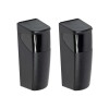
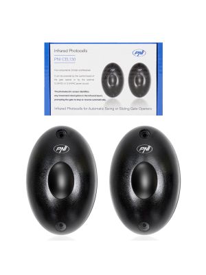
| PNI CEL135 photocell setPNI CEL135 is a set of photocells designed for integration into automatic gate opening systems (sliding or swinging gates). This type of equipment is part of the photoelectric sensor category, which detects the presence or passage of objects by interrupting an infrared light beam. In the context of car access automation, these photocells protect users and vehicles, ensuring the safe operation of the automated system. |
What are photocells and how do they work?Photocells are photoelectric devices that emit and receive a beam of light — in the infrared spectrum — between two components: a transmitter and a receiver. When the light beam is interrupted (for example, by a car or a person passing through the monitored area), the receiver detects this change and sends an electrical signal to the gate automation controller. This operation allows the automatic system to stop or reverse the movement of the gate, preventing accidents and damage to the equipment. Such a system is very useful for protecting automatic entrances and avoiding collisions with obstacles. |
|
| Main features of PNI CEL135 photocellsThe PNI CEL135 photocells use infrared technology and are composed of two units: a transmitter unit and a receiver unit. The transmitter operates independently powered by batteries, and the receiver connects to the gate automation control unit, usually at a supply voltage of 12–24 V AC/DC. The system has a detection distance of up to approximately 9 m, which makes it suitable for medium and large sized gates. The photocell housing offers an IP45 degree of protection against external factors, which allows use in outdoor environments with various atmospheric conditions. |
Installation and configuration in the automation systemThe installation of PNI CEL135 photocells involves mounting the two units face to face, on the posts or side structures of the gate, at a height that allows for the effective detection of vehicles and pedestrians. The transmitter and receiver must be correctly aligned so that the infrared beam is received without interruption. The receiver connects to the gate automation control unit, using the terminals dedicated to safety, and the power supply is carried out at the voltage accepted by the system. The configuration is simple, it is only necessary to verify correct operation by testing the gate's reaction to beam interruption. A correct installation ensures stable detection, reduces false alarms and contributes to the safe and reliable operation of the entire automated system. | |


FAST SHIPPING
You'll have your ordered products in just a few days.
MONEY BACK GUARANTEE
If you decide to return your products, you will get all your money back.
ONLINE SUPPORT 24/7
Contact us and we will answer to all your questions about orders, returns or warranty.